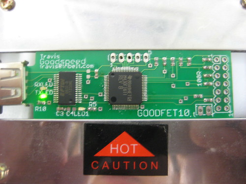
GoodFET10
The GoodFET10 is the first hardware revision of the GoodFET. Like all first-run boards, it has a few errata that must be patched before use. These inconveniences will be fixed in the GoodFET11.
CAD Files
Eagle CAD 5.x files for the design can be found in /branches/goodfet10 of Subversion, or as goodfet10.zip.
Bill of Materials
| Quantity | Package | |
| 1 | SSOP28 | FT232R |
| 1 | QFP64 | MSP430F1611 or 1612 |
| 2 | 0603 | 0.1μF Decoupling Capacitors |
| 3 | 0603 | LED |
| 2 | 0603 | 330R LED Series Resistors |
| 5 | 0603 | 47K Pull-up Resistors |
| 6 | 0603 | 100R JTAG Series Resistors |
Also, one 47K through-hole resistor and a 32.768kHz crystal are required to patch errata.
Construction
Construct
as described on the
following Flickr image's annotations, then patch as described
in the Errata section.
Errata
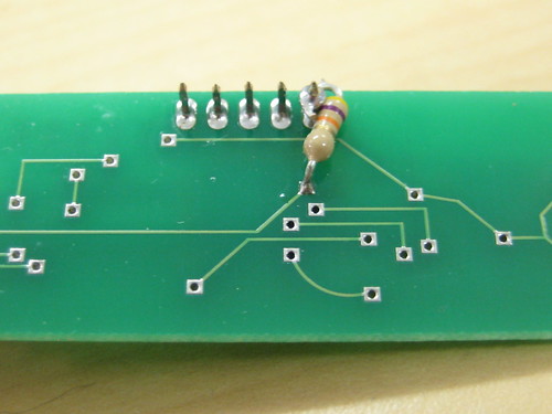 The GOODFET10 is missing a 47K pull-up resistor on the !RST pin of the MSP430F161x
chip. Solder one like so.
The GOODFET10 is missing a 47K pull-up resistor on the !RST pin of the MSP430F161x
chip. Solder one like so.
Further, no crystals are present on this board. A 32.768kHz crystal must be patched onto the XIN/XOUT pins.
The board as first manufactured was too thin, so a wedge or a crimped USB extension cable is necessary for a tight fit. Future runs will be made at 0.078'' thickness.